Pulse radiolysis set-up based on the 10 MeV electron linear accelerator (LAE 10)
 Measurement Room
|
Pulse radiolysis is an invaluable tool for studying the kinetics and spectra of transient chemical species. It has found a broad range of important applications in chemistry and biochemistry, extending far beyond the scope of radiation chemistry to which it was first applied.
With the advent of microprocessors, all aspects of the generalized experiment are susceptible to computer control. On this page we describe a computer-controlled pulse radiolysis system based on a fast digital storage oscilloscope (DSO). The oscilloscope produces a sufficient number of time points that multiple time scales can be generated by the computer from a single kinetic trace originating from DSO. Thus, one can in principle, with a single kinetic trace, resolve time constants from a few nanoseconds to tens, or even hundreds of microseconds. The simultaneous recording transient absorption data on multiple time scales is valuable for saving both experimental time and the amount of valuable samples.
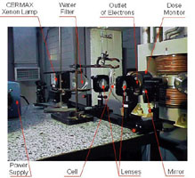
The Measurement Room, with accelerator gun, analytical light source lamp, dose meter and other devices, is separated from the operator room by a shielding wall and fiber optic connectors used for noise interference minimization.
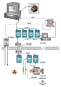
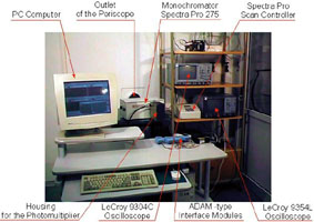
Analytical light, after passing the measurement cell, the periscope and the monochromator SpectraPro-275 (Operating Room)(controlled by the host PC) is converted to electric current signal in the photomultiplier Hamamatsu R-955. The signal, after subtraction of the reference light and signal amplification (DI) (1, 10 or 100 ´), is measured by the LeCroy 9354AL oscilloscope. Other analog signals (reference light-I0 and dose monitor) are measured using AD converters in ADAM modules (Advantech).
All peripherals are connected to the host computer (PC) using two types of interfaces: the GPiB-Parallel Bus and RS232/RS485 Serial Buses with the optical isolation. Fast oscilloscope LeCroy 9354AL is connected to the PC using parallel bus GPiB. This bus is also used for connecting the HV Power Supply PS310 (not shown on scheme). Other peripherals are connected to the PC using single RS485 Serial Communication Port.
Digital signals, pre-trigger, dose strobe, reference light strobe, are sent from the host computer to target elements using digital (open collector) outputs through specialized ADAM modules. The pre-trigger pulse is sent to the accelerator using fiber optic connections. The trigger signal from the accelerator, after passing through fiber optics and converters, is sent to the LeCroy 9354AL oscilloscope. The monochromator, equipped with RS232 interface, is connected to the host PC using the ADAM 4521 addressable module that converts RS485 standard to RS232 standard. The program RD2000, which controls pulse radiolysis setup, works under Windows 9X/NT operating system. This program was created using Delphi 3.0 (Borland) Pascal type programming tools.
 Operating Room
 Operator Desktop
|
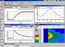
The Operator Desktop (RD2000) consists of five sub-windows: One-shot data, for the actual measured kinetics; Final data, for averaged data which are displayed after each accelerator shot at the selected wavelength; D3Form, for the kinetics vs. wavelength mapping; Spectral Data, for the spectrum obtained from the averaged kinetics data, at the selected time; Monochromator (not shown), for controlling of data transfer from/to peripherals connected to the serial port. This window is used in the case of emergency, and normally is not shown on the operator desktop.
Oscilloscope Dialog Window (not shown)(RD2000) pages are dedicated to the communication with GPiB peripherals: LeCroy 9354 and HV Power Supply PS310. Operator has several options: changing active channel parameters, trigger parameters and active buffer parameters. The active buffer parameters are used for positioning the front of the electron pulse accurately at the 20% time scale position point. In the current version, the buffer length and the time scale are fixed parameters.
Final Data window shows unwrapped box with optional values of the time scale parameter for the displayed kinetics. In the current version the system collects data on 11 time domains: starting from 100 ns and ending on 200 ms. All kinetics are stored in 200-points data buffer per each time domain.
The operator can choose independently any time scale for each window, i.e. One Shot Data, Final Data, D3Form1. Data, in the Data Spectrum Window, are displayed accordingly with the position of the horizontal marker (time positioning) on mapped data.
